|
|
|
|
The next step in the restoration was to build up the chassis. The original frame (see tear down) was too far gone, so a better one was found. Since the original chassis was a 1914, we tried to use 1914 parts as much as possible. Click on any photo to enlarge, then use your "Back" button to get back to this page
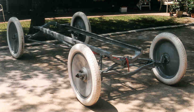
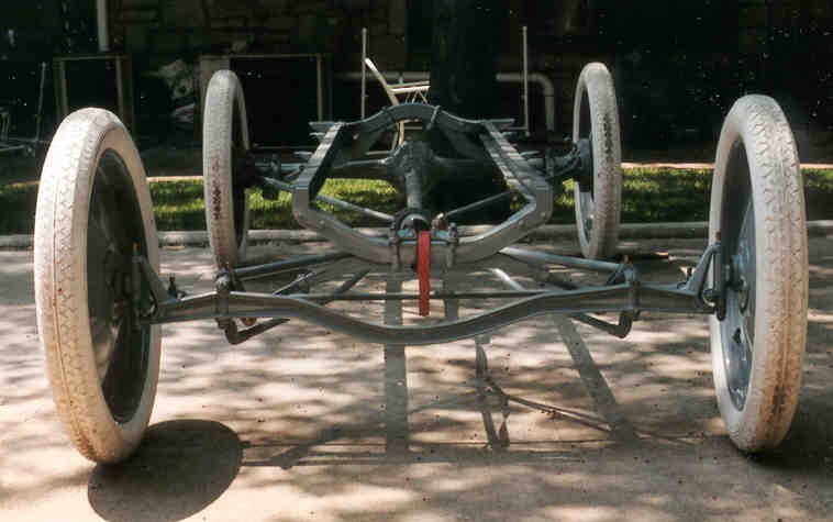
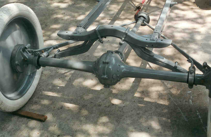
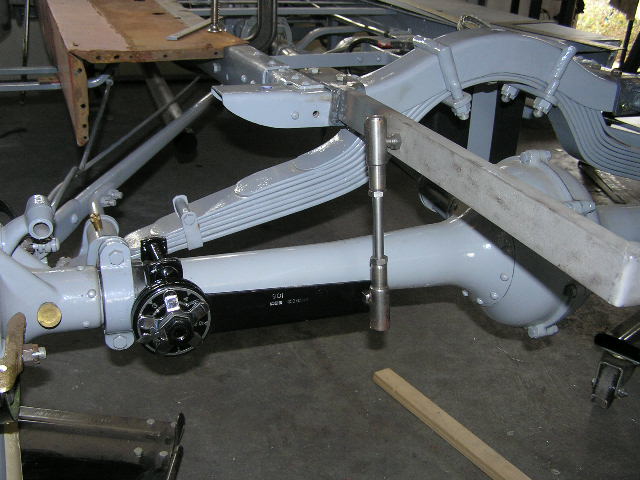
This shows the chassis after rebuilding the front and rear suspension and the rear axle. Pictures of the car from the 1920's show it with disk wheels (see History), which were a prized accessory during that period. We have used Disteel wheels in the restoration.
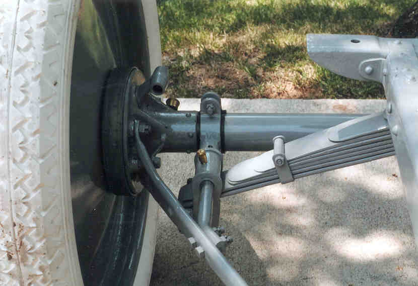
The front axle was bent to provide clearance for the crank handle (see axle bending). This is an original Dodge Bros. axle and the spring leaves are tappered, which are correct for 1914.
This shows the front lowering brackets. The bracket attached to the radius rod was built up with the welder and then turned down in the lathe. New bolts were made for the spring attachment point. Later, I will split the wishbone to provide better access to the deep sump on the engine.
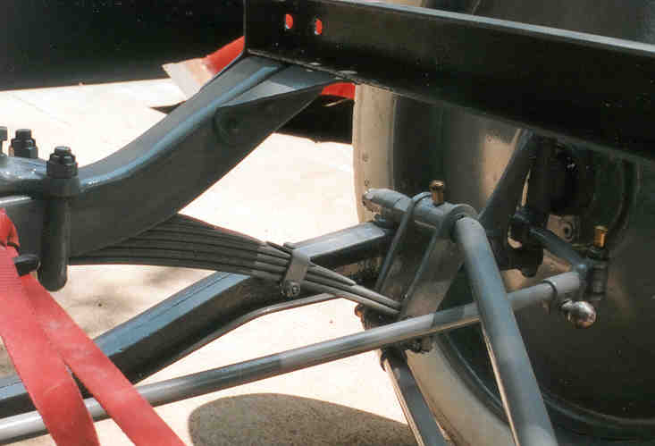
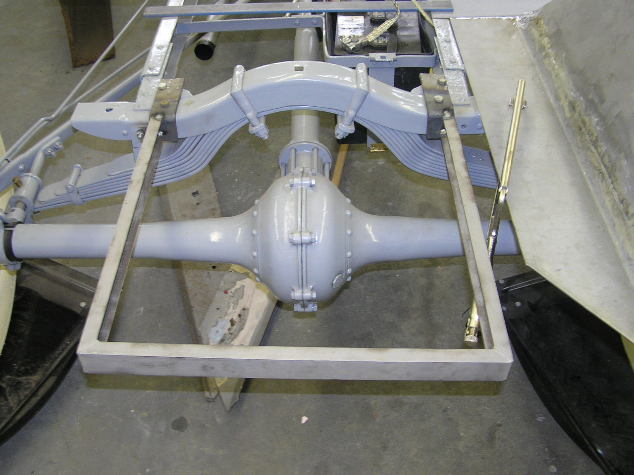
This shows the details of the rear lowering blocks (note the original spring perch). The radius rods were shortened for the Muncie transmission and a solid chunk of steel was used inside to provide extra strength where the rear suspension attaches.
This period ad for Laurel lowering brackets shows a strong similarity to the ABC brackets.
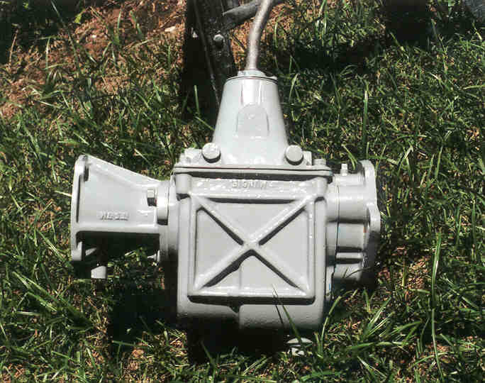
In keeping with the cars origins, a 1913-14 differential housing was used. To move the spring forward, the frame was telescoped as shown in the Laurel ad above. This method is better than using the extra crossmember which cracked the original frame (see tear down).
I was well into the restoration when I decided to build this extension onto the frame. It not only gives needed support to the tail portion of the body, it also provided a mounting place for the shocks, tail lights, turn lights and an extra support for the rear fenders.
This is an old ad for Hartford shocks. Note that the shock mounts on the frame, not the axle. I couldn't find an easy way to convert mine, so I devised my own mountings.
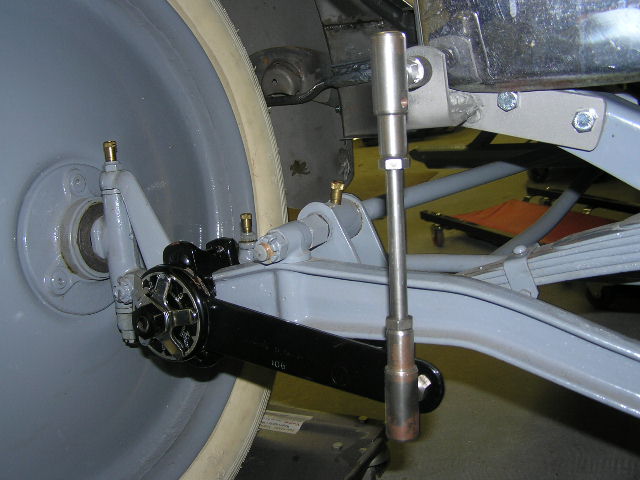
This shows an initial mounting of the rear shocks, which was later modified. All of the shock links had to be shortened after the mounting was finalized.
I got these shocks from Shaffer's in Central Point, Oregon. They came with brackets that were supposed to work even on a lowered T. They didn't, so I made these mounting brackets for the front.
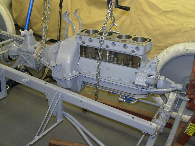
This is the rebuilt Muncie transmission. The ears on the front will have to be cut off since they interfere with the action of the emergency brake linkage.
|